Servo Motors are widely used where precise control is required such as robots, Automated Machineries, robotic arm etc. However, the scope of the servo motor is not limited to this much and can be used in many applications.
In this tutorial, we will interface Micro Servo Motor with Atmega16 AVR Microcontroller using Atmel Studio 7.0. The servo motor is rated to work in 4.8-6V. We can control its angle of rotation and direction by applying pulse train or PWM Signals. Note that the servo motors cannot move for full 360 degree rotation, so they are used where continuous rotation is not required. The rotation angle is 0 -180 degrees or (-90) – (+90) degrees.
Components Required
SG90 Tower Pro Micro Servo Motor
Atmega16 Microcontroller IC
16Mhz Crystal Oscillator
Two 100nF Capacitors
Two 22pF Capacitors
Push Button
Jumper Wires
Breadboard
USBASP v2.0
Led(Any Color)
Pin Description of Servo Motor

Red = Positive Power Supply (4.8V to 6V)
Brown = Ground
Orange = Control Signal (PWM Pin)
Circuit Diagram
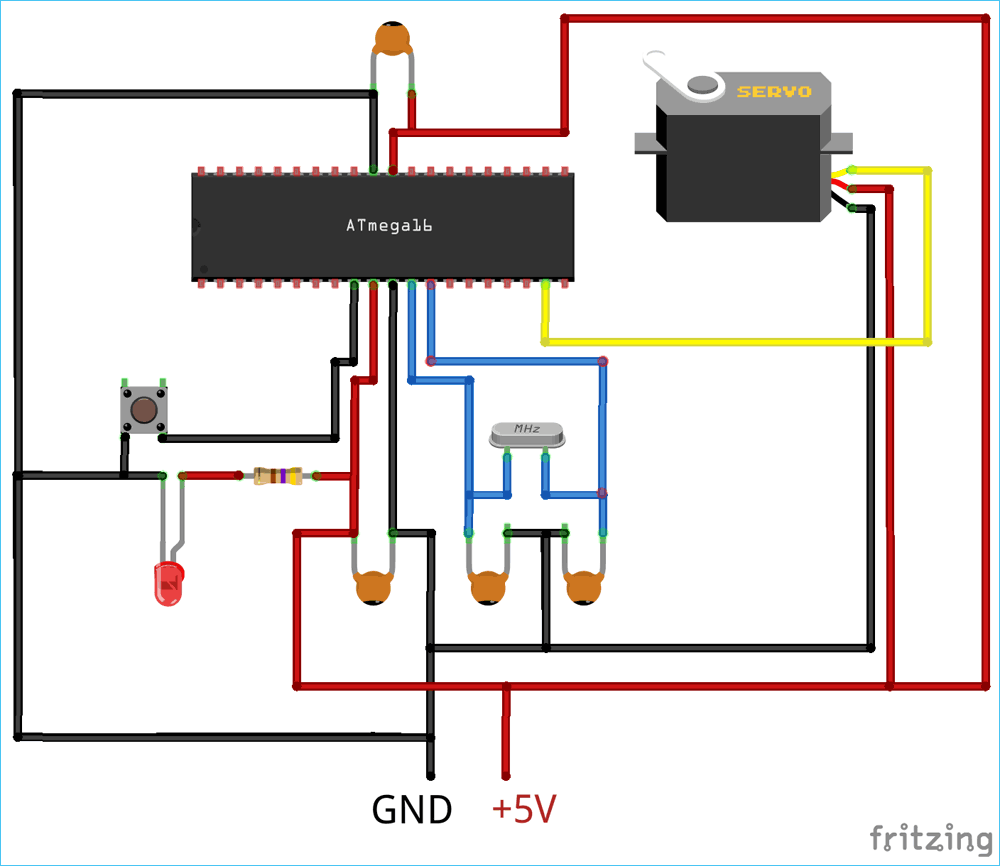
Connect all the components as shown in the diagram below to rotate the Servo motor using AVR Microcontroller. There are four PWM Pins, we can use any PWM pin of Atmega16. In this tutorial we are using Pin PD5 (OC1A) for generating PWM. PD5 is directly connected to orange wire of servo motor which is input signal pin. Connect any color led for power indicator. Also, connect one push button in Reset pin for resetting Atmega16 whenever required. Connect Atmega16 with proper crystal oscillator circuit. All the system will be powered by 5V supply.

Complete setup will look like below:

Controlling Servo Motor with AVR ATmega16
Like Stepper Motor, Servo motor doesn’t need any external driver e.g. ULN2003 or L293D motor driver. Just PWM is enough to drive the servo motor and it is very easy to generate PWM from a microcontroller. The torque of this servo motor is 2.5kg/cm, so if you require greater torque then this servo is not suitable.
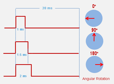
As we know that the servo motor seeks a pulse every 20ms and the length of the positive pulse will determine the rotation angle of the servo motor.

The frequency required to get the 20ms pulse is 50Hz (f = 1/T). So for this servo motor, the specification says that for 0 degree we need 0.388ms, for 90 degree we need 1.264ms and for 180 degree we need 2.14ms pulse.
To generate specified pulses we will use Timer1 of Atmega16. The CPU frequency is 16Mz but we will be only utilizing 1Mhz as we don’t have much peripherals connected to microcontroller and there isn’t much load on microcontroller, so 1Mhz will do the job. The Prescaler is set to 1. So the clock is divided as 1Mhz/1 = 1Mhz (1uS) which is great. Timer1 will be used as Fast PWM Mode i.e. Mode 14. You can use different modes of timers to generate desired pulse train. The reference is given below and you can find more description in Atmega16 Official Datasheet.

To use Timer1 as fast PWM mode we will need the TOP value of ICR1 (Input Capture Register1). To find the TOP value use formula given below:
fpwm = fcpu / n x (1 + TOP)
This can be simplified to,
TOP = (fcpu / (fpwm x n)) – 1
Where, N = Value of Prescaler set
fcpu = CPU Frequencey
fpwm = Servo motor pulse width which is 50Hz
Now calculate the ICR1 value as we have all value required,
N = 1, fcpu = 1MHz, fpwm = 50Hz
Just put the values in above formula and we will get
ICR1 = 1999
This means to attain maximum degree i.e. 1800 the ICR1 should be 1999.
For 16MHz crystal and Prescaler set to 16, we will have
ICR1 = 4999
Now let’s move on to discuss the sketch.
Programming Atmega16 Using USBasp
Complete AVR code for controlling Servo Motor is given below. Code is simple and can be understood easily.
Here we have coded the Atmega16 to rotate the servo motor from 00 to 1800 and coming back again from 1800 to 00. This transition will complete In 9 steps i.e. 0 – 45 – 90 – 135 – 180 – 135 – 90 – 45 – 0. For delay, we will be using the internal library of Atmel Studio i.e. <util/delay.h>
Connect your USBASP v2.0 and follow the instructions in this link to program Atmega16 AVR Microcontroller using USBASP and Atmel Studio 7.0. Just build the sketch and upload using external toolchain.
Complete code with Demonstration Video is given below.
Code
#define F_CPU 1000000UL
#include<avr/io.h>
#include<util/delay.h>
void main()
{
//Configure TIMER1
TCCR1A|=(1<<COM1A1)|(1<<COM1B1)|(1<<WGM11); //NON Inverted PWM
TCCR1B|=(1<<WGM13)|(1<<WGM12)|(0<<CS11)|(1<<CS10); //PRESCALER=1 MODE 14(FAST PWM)
ICR1=19999; //fPWM=50Hz (Period = 20ms Standard).
DDRD|=(1<<PD4)|(1<<PD5); //PWM Pins as Out
while(1)
{
OCR1A=0; //0 degree
_delay_ms(1000);
OCR1A=600; //45 degree
_delay_ms(1000);
OCR1A=950; //90 degree
_delay_ms(1000);
OCR1A=1425; //135 degree
_delay_ms(1000);
OCR1A=1900; //180 degree
_delay_ms(1000);
OCR1A=1425; //135 degree
_delay_ms(1000);
OCR1A=950; //90 degree
_delay_ms(1000);
OCR1A=650; //45 degree
_delay_ms(1000);
}
}


This comment has been removed by a blog administrator.
ReplyDeleteThis comment has been removed by a blog administrator.
ReplyDelete